此為 Smart Battery Selector Specification Revision 1.1 第六章節的中文翻譯
對翻譯有問題的請參閱前幾篇~
======
6. Example Implementations 實現示例
This section is intended to provide a closer look at some possible implementations of a battery selector.
本部分旨在提供電池選擇器的某些可能實現方案更進一步的觀察。
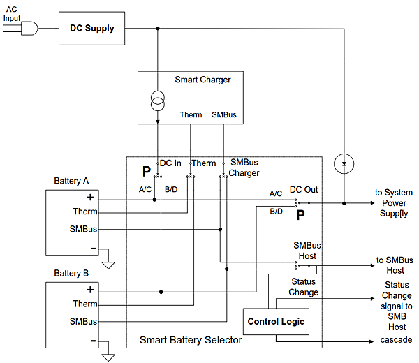
6.1. Sample Battery Selector Diagram
This drawing shows, at a relatively high level, the inner workings of a stand alone battery selector. It is not intended to provide sufficient detail to construct a selector, but rather give a flavor of how it can be done.
該圖以較高的層次顯示了獨立電池選擇器的內部工作原理。 此圖並沒有打算提供充分的細節來構建一個選擇器,而是提供一種如何完成選擇器的概念(讓人聞聞香)。
This particular design will support two batteries, but two devices can be cascaded together to support up to four batteries. The switches labeled “P,” are power switches and probably would be external to the device.
這種特殊的設計將支持兩個電池,但是兩個設備可以級聯(cascade)在一起以支持多達四個電池。 標有“ P”的開關是電源開關,可能在設備外部。

6.2. Battery Selector Emulation
This section illustrates two examples where the keyboard controller emulates the smart battery selector functions: power switching and communications selection. In both of the following examples, a keyboard controller is acting as the system’s SMBus host controller.
本節說明了兩個示例,其中 鍵盤控制器 模擬了 智能電池選擇器 的功能:電源切換和通信選擇。 在以下兩個示例中,鍵盤控制器 都充當系統的SMBus主機控制器。
By intercepting commands directed to a battery selector, the keyboard controller can translate them into an appropriate action emulating a smart battery selector.
通過截取指向電池選擇器的命令,鍵盤控制器 可以將它們轉換為 模擬智能電池選擇器 的 適當操作。
For example, the keyboard controller in example 6.2.1 can readily report the system’s status (for example, which battery(s) is present) or read each battery’s characteristics (for example, fuel gauge information). Therefore, to emulate a smart battery selector, all that is needed is a keyboard controller that accepts standard battery selector messages, translates them into appropriate hardware specific actions and returns standard battery selector messages.
例如,例6.2.1中的鍵盤控制器可以迅速地報告系統狀態(例如,哪個電池存在)或讀取每個電池的特性(例如,電量計信息)。 因此,要模擬智能電池選擇器,只需要一個鍵盤控制器即可接受標準電池選擇器消息,並將其轉換為 適當的硬件特定操作 ,並返回標準電池選擇器訊息。
6.2.1. Power Switching
This circuit uses the Safety Signal pin of the Smart Battery with a logic circuit to detect the presence of a battery. It also detects the output voltage of the battery, so that if the battery is removed or its output falls below the minimum useable voltage battery cutoff voltage (which is equal to VREF), the circuit automatically switches to the other battery.
該電路使用智能電池的安全信號引腳和邏輯電路來檢測電池的存在。 它還檢測電池的輸出電壓,因此,如果卸下電池或者其輸出降至最低可用電壓或電池截止電壓(等於VREF)以下,電路會自動切換到另一塊電池。
(註:原文似乎少了一個or,翻譯採用補上『或』的翻譯,語意較符合常理)

6.2.2. Battery Communications Selection
There is only one “battery address” in the system, so, for systems with multiple batteries there must be a communications selection process. The following circuit shows one approach: the data lines are tied together and a selector switch, controlled by the keyboard controller, routes the clock to the appropriate battery. With the clock line of the non-selected battery held low, preventing it from responding to signals on the data line, communication with only the selected battery is possible.
系統中只有一個“電池地址”,因此,對於具有多個電池的系統,必須進行通信選擇過程。
以下電路顯示了一種方法:將數據線連(tie)在一起,並由鍵盤控制器控制的選擇器開關將時鐘路由到適當的電池。 在未被選擇的電池的時鐘線保持為低電平的情況下,防止其響應數據線上的信號,如此一來,只有與被選擇的電池進行通信是可能的。
This method requires the host (keyboard controller) to handle all battery communications and to periodically communicate with both batteries, since there is no way for the non-selected battery to alert the host that it has encountered a critical condition.
此方法要求主機(鍵盤控制器)處理所有電池通訊,並定期與兩個電池通訊,因為未選擇的電池無法警告主機已遇到嚴重狀況(critical condition)。

6.3. Combined Charger / Selector Component
Since the Smart Battery Charger and Selector functions are closely related, one possible implementation could merge the operation of these two components into a single device.
In this case, the selector commands described in Section 5 are mapped into the charger’s address space at command codes 0x21, 0x22, and 0x24 for SelectorState(), SelectorPresets(), and SelectorInfo(), respectively. Merging these two functions guarantees close cooperation between the selector and charger (especially useful for a system designed to charge multiple batteries autonomously without the host’s direct control) and may derive cost benefits from reduced component count. Some care should be taken, however, to ensure safe operation in all functional modes when combining the functionality of both components in a single device.
由於智能電池充電器和選擇器功能密切相關,因此一種可能的實現方式是將這兩個組件的操作合併為一個設備。 在這種情況下,第5節中描述的選擇器命令分別映射到充電器的地址空間中,分別用於SelectorState(),SelectorPresets()和SelectorInfo()的命令代碼0x21、0x22和0x24。 合併這兩個功能可確保選擇器和充電器之間緊密配合(對於在無需主機直接控制的情況下自動為多個電池充電的系統中特別有用),並且可以通過減少組件數量獲得成本收益。 但是,在將兩個組件的功能組合到一個設備中時,應注意確保所有功能模式下的安全操作。
One area of special concern for a combined charger and selector component is its operation when charging a battery. For an implementation where the charger is always on the same SMBus segment as the host (the most likely case), any request by the host to communicate with a battery other than the one being charged will necessarily require disconnecting the charger’s SMBus from the battery being charged.
In this situation, the charger / selector component must not accept any current or voltage requests from the other battery, and if for some reason the SMBus connection is not restored to the battery being charged, charging must be aborted after the communications timeout period as defined in the Smart Battery Charger Specification (e.g. 140 seconds minimum, 210 seconds maximum).
充電器和選擇器組件組合使用時,特別需要關注的一個領域是電池充電時的操作。
對於充電器始終與主機位於同一SMBus網段的實現(最可能的情況),主機與除了被充電電池之外的其他電池進行通信的任何請求,都必須將充電器的SMBus與正在充電的電池斷開連接。
在這種情況下,充電器/選擇器組件不得接受其他電池的任何電流或電壓請求,並且如果由於某種原因SMBus連接沒有恢復到正在充電的電池,則必須在定義的通信超時時間後中止充電, 如定義在智能電池充電器規範中的一樣(例如,最小140秒,最大210秒)。


 留言列表
留言列表


